Xds100 Serial

Programming the XDS100. Before you can use the XDS100 as an Emulator, you will need to program the EEPROM that is part of the XDS100. Once the EEPROM is.
- The XDS100 emulator provides JTAG access to serial number for each emulator. Studio v4 when used with XDS100. Code Composer Studio v4 can be.
- Introduction. The XDS100-class emulators are based on a device FT2232H that is a High-speed USB to a dual-channel UART, also commonly known as a USB to serial.
The XDS100 emulator is Texas Instruments ultra-low-cost USB-interface JTAG hardware reference design.
The XDS100 emulator provides JTAG access to Texas Instruments JTAG based devices.
It is compatible with Code Composer Studio development environment.
TI creates the reference design and our 3rd party partners create the JTAG emulator products for end use.
The XDS100s are available as discrete emulators, or can be embedded on a development card DSK, EVM, etc..
There are 3 versions of the XDS100. The XDS100v1 is the original XDS100 design. The XDS100v2 is an updated XDS100 design with more capability. The XDS100v3 is an updated XDS100v2 design with support for the 1149.7 protocol.
Performance of the XDS100 is lower than the XDS510 and XDS560. This means that program and data downloads will take a longer time than with XDS510 and XDS560 emulators. Also, stepping in C and Assembly will be slower with XDS100 when compared to XDS510 or XDS560 emulators.
The Texas Instruments reference design for XDS100 has the following features Please check your vendor for hardware details :
Debug features Emulation Connect/Disconnect, Read/Write memory, Read registers, Load program, Run, Halt, Step, Software and Hardware Breakpoint support, Real-Time Mode
Compatible with Code Composer Studio.
Support for targets with 1.8v and 3.3v IO voltages.
Support for JTAG reset / wait-in-reset boot-modes using the two EMU pins sampled by the nTRST pin.
Support for Power-on reset boot-modes using the two EMU pins sampled by the TVD pin.
Support for the configuration of the EMU pin features through Code Composer Studio Setup connection properties dialogs similar to those for the XDS560 Rev-D cable.
Support for target power-loss detection via the TVD pin even when Code Composer Studio is not running, and applying boot-modes at Code Composer Studio start-up.
XDS100v1 emulators are only recommended for users who need to use Code Composer Studio v3.3, anyone using Code Composer Studio v4 or later should consider an XDS100v2 or later emulator due to the increased performance. Some of our 3rd Party partners have implemented XDS100v2 emulators that can also operate in v1 mode for compatibility with Code Composer Studio v3.3.
XDS100v3 emulators are recommended for users who require support for IEEE 1149.7, most devices do not require this.
XDS100v2 is the default recommended XDS100 emulator.
The Texas Instruments reference design for XDS100v1 has the following features. Please check with your vendor as to whether the all of the below features are supported:
All of the XDS100 General Features
Support for USB Full Speed 12 Mbits/s
Support for multiple FTDI devices CCSv4 only
Support targets with 14-pin TI JTAG connector used by Texas Instruments embedded processors.
Support for the following processors cores: TMS320C28x, TMS320C54x, TMS320C55x, TMS320C64x, TMS320C674x and TMS320C66x.
The Texas Instruments reference design for XDS100v2 has the following features. Please check with your vendor as to whether the all of the below features are supported:
Support for USB High Speed 480 Mbit/s
Support targets with 14-pin TI JTAG connector or 20-pin TI JTAG connector as used by Texas Instruments embedded processors. Please check your vendor for hardware details
Support for the following processor cores: TMS320C28x, TMS320C54x, TMS320C55x, TMS320C64x, TMS320C674x, TMS320C66x, ARM 9, ARM Cortex cores: A A8, A9 and A15, M M0, M3 and M4 and R R4 and R5. Support for the cores was incrementally added across the releases - check the release notes for the version you are using.
Supports cable-break detection
Supports target power loss detection
Support for multiple FTDI devices
LED light to indicate active USB connection
Support for Code Composer Studio v4 and newer Does not support Code Composer Studio v3.3
Note: As of 4/28/2010, the CPLD update was issued. Please see XDS100 Q:_How_can_I_update_the_CPLD_on_my_XDS100v2.3F
The Texas Instruments reference design for XDS100v3 has the following features. Please check with your vendor as to whether the all of the below features are supported:
IEEE 1149.7 capable emulator with a USB interface.
Can function as an 1149.7 adapter for use with existing scan controllers.
Software compatible with XDS100v2 except link delay and IEEE 1149.7 modes.
Physical jumper to select emulator or adapter mode.
Operates in 1149.7 Class 4, up to 25MHz.
LED to indicate IEEE 1149.7 Class 4 operation.
LED to indicate operation in adapter mode.
It does not support Real Time Data eXchange RTDX or High Speed RTDX HSRTDX
It does not provide hardware support for TCLKR external clocking
Cores NOT supported: ARM 7, ARM 11, TMS320C24x, TMS320C55x, TMS320C670x, TMS320C671x, TMS320C672x, TMS320C64x note that TMS320C64x is supported and other cores not listed as supported.
It cannot read the value of the EMU0/1 pins, so long profiling operations that use the EMU0/1 pins to handle counter overflows will not be possible.
JTAG Clock TCLK frequency other than default JTAG frequency 1Mhz
XDS100 Installation Instructions
Installation for Code Composer Studio v6
All drivers are installed when XDS100 is selected during installation.
Installation for Code Composer Studio v5
For CCSv5.5 all drivers are installed when XDS100 is selected during installation. For CCSv5.1, 5.2, 5.3 and 5.4 make sure to check for updates in CCS and install the latest TI Emulation update if support for XDS100v3 is needed.
Code Composer Studio v5.1.x Support XDS100v1, XDS100v2 and XDS100v3 hardware
Code Composer Studio Release/Version
Code Composer Studio v5 page and newer
Additional SW patch required for XDS100v3 support
A. Install Code Composer Studio 5.1.x XDS100v1 and XDS100v2 support is included as per the table above before connecting XDS100 USB hardware.
B. Install the EmuPack with XDS100v3 support.
C. Connect the XDS100 hardware
Make sure the Code Composer Studio 5.1.x and EmuPack with XDS100v3 support is installed FIRST before plugging in the XDS100 HW to the PC.
Connect USB cable from the PC to the XDS100 hardware. Connect the JTAG to the target board be careful to plug it in correctly: pin 1 should go to pin 1. Red strip usually indicates the side of pin 1
You will notice small popups to inform user that USB hardware is recognized and installed correctly. No input are required.
D. Setup Code Composer Studio v5.1.x
Start Code Composer Studio and create a new target configuration. See Quick Tips Target_Setup.C2.A0
Select XDS100 as connection type either XDS100 v1, XDS100 v2 or XDS100v3
Installation for Code Composer Studio v4.x
Code Composer Studio v4.x Support XDS100v1 and XDS100v2 hardware
Code Composer Studio v4.1 and newer
No additional SW required for XDS100 support
- Code Composer Studio 4.2.2 and newer -
Code Composer Studio v4.2 and newer
A. Install Code Composer Studio 4.x XDS100 SW support is included as per the table above before connecting XDS100 USB hardware.
B. Connect the XDS100 hardware
Make sure the Code Composer Studio 4.x is installed FIRST before plugging in the XDS100 HW to the PC.
C. Setup Code Composer Studio v4.x
Select XDS100 as connection type either XDS100 v1 or XDS100 v2
Installation for Code Composer Studio v3.3 XDS100v1 Hardware Only
Code Composer Studio v3.3 Support XDS100v1 HW only
CCS v3.3 Platinum Edition TI part : TMDSCCSALL-1
Included with CCS Service Release 12 and newer.
CCS v3.3 for C2000 Full Version version 3.3.78.2 TI part : TMDSCCS2000-1
XDS100 SW required. Download here.
CCS v3.3 for C2000 DSK Version version 3.3.81.28, 3.3.83.16 or newer
XDS100 SW included in CCS Installation. No additional SW required.
Note: Code Composer Studio v3.3 ONLY supports XDS100v1 hardware emulator. XDS100v2 hardware is NOT supported on Code Composer Studio v3.3.
Note: Blackhawk has a model D version of XDS100v2 which can be configured to work as a v1 or v2 product. They provide a utility to re-program the device to act as a xds100v1, so the same product can be used with both CCS3.3 and CCS4. The firmware update utilities can be found on their Blackhawk XDS100 Support Page.
A. Install Code Composer Studio and XDS100 Software before connecting XDS100 USB hardware.
Install the Code Composer Studio version, service release and/or XDS100 SW as detailed in the table below prior to connecting the XDS100 SW.
Make sure the XDS100 Software is installed FIRST per the table above before plugging in the XDS100 HW to the PC.
C. Setup Code Composer Studio v3.3
Select CC Setup icon from the desktop.
From the filters panel, select the platform xds100usb emulator. This will give you a list of predefined configurations. Select the one appropriate for your device
Save your configuration and exit CC Setup
In Code Composer Studio, go Debug-- Connect. Note: connect to target may take long time 5 seconds for the first time XDS100 USB is connected to target. It is not the case with subsequent connect operations.
XDS100 debuggers suffer a severe performance impact when using Virtual Machines VMware, Virtualbox, Parallels, etc. and Linux as a guest OS. Additional details are shown at this page.
While loading a large program or program section, the file load status bar may appear frozen when it is not frozen. The status bar is showing section load start and completion.
When a second FTDI device is plugged in ex: FT232RL, and it receives a lower chain number, the XDS100 SW will address it instead of the FT2232 used by the XDS100. Solution: only plug the XDS100 HW into the PC. This has been fixed with Code Composer Studio v4 support for the XDS100v2.
XDS100 SW Driver does not install properly under Windows Vista 64 bit using CCSv3.3
If Option under CCSv3.3 connect to target at CCS startup is enabled and c674x target board is connected, then the following error is reported when you try to Disconnect for the 1st time. It works fine on 2nd attempt to disconnect. Note, this has been fixed for CCS v4.
Error during: Execution, Control,
This error was generated by TI s USCIF driver.
This utility failed to operate the adapter for a custom emulator.
The adapter returned an error for unknown reasons.
When selecting OMAPL137 configuration in CCS 4.0.2, the GEL files cause the connection to be hung. Remove the GEL file from the target configuration.
ETB for OMAPL137/8 is not working. Error of ETB definitions cannot be loaded. Device not supported. is reported. ETB11 for OMAPL137/138 is not supported at this time.
When installating XDS100v2 patch via update manager, CCS says that the feature is not digitally signed. Continue installation.
Target power loss detection is not working in CCS v4.1/v4.1.x. This has been fixed in CCS v4.2.
Adaptive clocking use with OMAPL138/ARM9 cores connection reliability varies by card. This results in connection errors. A fix has been identified by upgrading the CPLD on XDS100v2 designs. Please see XDS100 Q:_How_can_I_update_the_CPLD_on_my_XDS100v2.3F
Check whether the installation process was followed.
Please check the FAQ questions below. Troubleshooting FAQ
Please check the section regarding Troubleshooting CCS.
Check your Windows System Devices. When properly installed, the XDS100 should look like the below image. If the XDS100 does not show up in the Windows device manager, then it is likely that the XDS100 was not programmed properly contact manufacturer or that there is a conflict with another FTDI based USB device see FAQ below for details.
Check USB cable or change the USB port the emulator is connected
You may want to check the VID/PID EEPROM was programed correctly
SW Update for improved performance.
Where to get an XDS100 / Where to buy an XDS100
Spectrum Digital, Inc., offers an XDS100v3 USB CJTAG/JTAG Emulator here
Olimex LTD, manufactures and sells a low-cost XDS100v3 here
Your Neighbor Tech, offers an XDS100v3 in china mainland with black plastic shell.here
Ashling s Opella-XDS100v2 is now available. Check it out here and buy here
Blackhawk has one available and our latest model supports both CCS v3.3 and v4., so no more deciding which model to buy
Olimex manufactures and sells an XDS100v2 debugger here
Spectrum Digital, Inc., offers an XDS100v2 USB JTAG Emulator here
TI Estore has a 14 pin TI or a 20 pin compact TI version available.
How to make an XDS100 / How to build an XDS100 hardware emulator
You can make your own XDS100 by using the schematic and programming instructions below.
XDS100v3 only recommended for cJTAG based devices
Q: Where can I get the design / schematic / BOM for the XDS100v3.
A: It is available from here registration required.
The design files schematic, gerbers, etc. are provided. Scrambled FPGA VHDL is also included.
Please read the included readme for details.
Q: What should the USB device s UID VID/PID be.
A: The EEPROM needs to be programmed for a VID 0403 PID A6D1. The device name string should be, Texas Instruments Inc.XDS100 Ver 3.0.
A: FTDI has a utility called MProg. See here. To program the FTDI chip you will need a MPROG template file that can be downloaded from this link.
Q: I want to put an XDS100v3 on my EVM / DSK / card. Can I do this.
A: Yes, but please make sure to re-use the entire XDS100 design as-is to ensure compatibility with the existing software.
Q: Where can I get the design / schematic / BOM for the XDS100v2.
The design files schematic, gerbers, etc. are drawn in the program KiCAD. PDF schematic is included. Bill of Materials BOM is included. MPROG script file is included. CPLD VHD and JED sources are included.
Note as of 4/28/2010, the design package was updated with new CPLD source code. This is to fix the issues related to Adaptive Clocking on ARM9.
A: The EEPROM needs to be programmed for a VID 0403 PID A6D0. The device name string should be, Texas Instruments Inc.XDS100 Ver 2.0.
A: FTDI has a utility called MProg. See here. To program the FTDI chip you will need a MPROG template file that can be downloaded from this link.
Q: XDS100-based C5505 and C5515 EzDSP USB Stick does connect when using Target Connect
I get: Error connecting to the target: Error 0x80000240/-600 Fatal Error during: Initialization, OCS
A: This can happen if the FDTI USB driver have not been properly uninstalled / re-installed i.e. if CCSv4 uninstall did not complete properly. I resolved it by going to Device Manager then right click on:
TI XDS100 Channel B - Uninstall then TI XDS100 Channel A - Uninstall Then it re-installed itself when re-connecting the XDS100-based USB stick and Target Connect worked afetr re-starting CCSv4
Q: I want to put an XDS100v2 on my EVM / DSK / card. Can I do this.
A: Yes, but please make sure to re-use the entire XDS100 design as-is to ensure compatibility with the software. Removing the CPLD implementing with discrete logic will result in a design that is just as complex and expensive as using the CPLD.
Q: Can I use port B as a UART.
A: Yes. The TI XDS100v2 reference design uses the port A of the FTDI2232H to be for JTAG. This leaves the port B available for use either to program the CPLD and/or for use as a UART. The XDS100v2 design puts the CPLD JTAG programming on a selected number of pins see XDS100v2 readme for details. This allows the CPLD to be programmed via the FTDI device, greatly simplifying manufacturing.
Please note that there is a known issue with the current XDS100v2 reference design with the placement of the BCBUS. If you plan to use the port B, please check the readme of the XDS100v2 reference design for details. Generally, a serial port on BCBUS should connect the CPLD as follows: BCBUS1 - CPLD TCK, BCBUS2 - CPLD TDI, BCBUS5 - CPLD TDO, BCBUS6 - CPLD TMS.
Please note that using UART mode simultaneously with Code Composer Studio v4 has NOT been tested on the XDS100v2 design and is not officially supported. Experience with C2000 ControlCards which implement this functionality indicate the FTDI driver can handle such an interaction. The C2000 control card does implement a serial port simultaneous with JTAG, but it is done with an XDS100v1 design. There is a thread on the forum at 1. The FTDI driver gives each half of the FTDI chip a seperate USB handle and USB endpoint, so they are essentially independent. The FTDI supplied software is the software that is needed to get this support; there is no TI specific software needed for this support.
Q: I see both 14 pin and 20 pin compact TI headers. Do I need both.
A: Both are in the reference schematic for testing Code Composer Studio support. In the TI prototypes, we populate just one of the 2 headers. This allows use to test the extended capability available with the 20 pin connection. Please use the header that is needed for your target card.
Q: Where can I get the schematic for the XDS100v1.
A: The C2000 control card schematics implement an XDS100 design optimized for C28x processors. The design is available as part of their baseline SW packages. These can be downloaded here
A: The EEPROM needs to be programmed for a VID 0403 PID A6D0. The device name string should be, Texas Instruments Inc.XDS100 Ver 1.0.
For 28x development cards, you may want to see this post
Frequently Asked Questions FAQ
Q: Where can I find out more about Emulators which are compatible with TI devices.
A: A general overview of TI emulation capabilities is here. For additional performance and capabilities, you may wish to review the XDS510 and XDS560 product lines which support TI devices.
Q: I would like to purchase a faster emulator, which one is recommended.
A: TMS320C28x: The Spectrum Digital C2000 XDS510LC JTAG emulator is available, details may be found here. The Blackhawk C2000 USB controller TI part TMDSEMU2000U is available from TI here.
A: TMS320C674x: The Blackhawk XDS560 TI part TMDSEMU560U for USB and TI part TMDSEMU560PCI for PCI are available from TI here. The Spectrum Digital XDS510 TI part TMDSEMU510U for USB is available from TI here.
Q: On the c28x, C674x, and C64x processor, does the XDS100 support Real-Time Mode.
A: Yes. Learn more about Real-Time Mode.
A: A couple of things can be done to improve performance under CCS. Generally, the goal is to minimze the amount of information transferred for every action
Make the disassembly window smaller or close the disassembly window. Stepping and general performance are better in the C language environment if the disassembly window is closed.
Minimize the number of registers shown.
Minimize the number of watch windows/variable windows.
Turn off mixed C/disassembly mode.
Make sure you are plugged into a High Speed USB2.0 port XDS100v2
Single step debugging is rather slow, therefore a better performance is obtained by running straight to specific points in your code by setting breakpoints in these locations.
Q: Does the XDS100 support debugging the C672x processor.
Q: Does the XDS100 support debugging the C24x processor.
Q: Does DSP/BIOS Real Time Analysis with RTDX work.
Q: When using DSP/BIOS and the Real Time Analysis setup for RTDX, I get the cpu graph and real time logs updating. Does this mean RTDX is working/supported on the XDS100.
A: RTDX is not supported on the XDS100. Please see the seciton What features does the XDS100 NOT support
Q: Can I use Advanced Event Triggering with XDS100.
Q: Can I plug more than one XDS100 multiple XDS100 into a PC.
With CCS v4.1 with the XDS100v2 SW and above you can plug more than one XDS100 on a single PC. This is not supported with CCSv3.3.
Each XDS100 must have a unique serial number. Run xds100serial.exe installed under CCSv4.1 /ccsv4/common/uscif/utility to get the serial number of each connected XDS100 emulator. Create Target Configuration for 2 emulators, Under connection properties, change emulator selection to select by serial number option. Enter the corresponding serial number for each emulator. Save and launch debugger.
With CCSv5, the xds100serial.exe utility is located in the folder /ccsv5/ccs_base/common/uscif
With older versions of CCS ex: CCS v3.3, there is a known issue see above which prevents the CCS XDS100 driver from seeing more than one XDS100 in a system. If more than one is in a system, only the first one is recognized.
xds100serial.exe can detect both XDS100v1 and XDS100v2 emulators.
Q: Can I use the XDS100 with Stellaris Cortex M3 devices.
Q: Can I use the XDS100v2 as JTAG simultaneously with the second port being a serial port UART.
Q: How can I use the XDS100v2 s second port as a serial port UART.
A: Ensure that there is a physical connection between the FTDI Port B TX and RX pins and your target serial device and then follow these steps:
Click Start, Right click on My Computer, and select Properties
Navigate to the Hardware tab of the System Properties dialog box and select Device Manager
In the list of devices, expand the group titled Universal Serial Bus controllers and look for a device named TI XDS100 Channel B
Right click on this device and select Properties
On the Advanced tab of this dialog box, ensure that the box labeled Load VCP virtual COM port is checked. Click OK when you are done.
Unplug and replug the XDS100v2
After the XDS100V2 has been re-connected, look for a group called Ports COM LPT in Device Manager. Expand this group and look for an entry labaled USB Serial Port COMXXX.
The COM number associated with this port is the one you want to use in Hyperterminal, PuTTy, or your favorite terminal application.
Q: How can I turn on adaptive clocking.
You can change the timeouts from the target as well. This is helpful if you get many timeout messages.
Q: My XDS100v2 does not work reliabily with the OMAPL138 / DM365 / ARM926 core
A: This can be caused by a variety of issues such as where the PLL is programmed to the use of Adaptive Clocking emulator. Usually, it is seen as a problem around the PLL setup. This is because the core PLL clock is changing. Example error message:
ARM9: Trouble Writing Memory Block at 0x1c40900 on Page 0 of Length 0x4: 0x00000004/-2030 marker 1026 Error during: Register, Access to an unknown or invalid register was attempted.
ARM9: GEL: Error while executing OnTargetConnect : target access failed.
Q: Can I use the XDS100 with OMAP-L138/C6748 EVM board.
Q: Does XDS100 work with Window 7 64 bit.
The current driver in XDS100v2 works with Windows 7 64 bit.
Q: Can I use the XDS100 without CCS. Is there an API to access it s functions.
We have some requests for an API to read/write targets, run/halt/step, load memory and handle STDIO. If you have requests, please post them in the support forum.
If you need API for accessing CCS, without a GUI, you may want to consider Debug Server Scripting
Q: Can I use the XDS100v1/v2 with CC13xx/CC26xx SimpleLink ULP devices.
A: No, only XDS100v3 supports the CC13xx/CC26xx device family. See CC13xx CC26xx Tools Overview for more details on debugger support for these devices.
Q: Where are the drivers for the hardware. Windows is asking for the drivers.
A: Please see Installation instructions and troubleshooting section.
Q: What operating systems are supported.
A: Please see System Requirements for Operating System support for CCS.
A: You have an older version of the XDS100 SW/CCS. The F28x Piccolo device configuration files are included in the latest versions of the SW. Please see the installation notes above.
Q: What does the windows messages look like in Windows XP upon successful installation.
A: See here. Note that after the first installation, there are no subsequent messages in Windows XP from the USB driver.
Q: I am using CCSv3.3 today. Can I get a driver to support XDS100 for my processor.
A: All new XDS100 development is being done on Code Composer Studio v4. Existing processors supported by XDS100 in CCSv3.3 will continue to be supported, but newer processors will not be added.
Q: Can I use Code Composer Studio v4 with XDS100.
A: There is a free license for Code Composer Studio v4 when used with XDS100. Code Composer Studio v4 can be downloaded from the Code Composer Studio v4 page. When you install CCS, you need to select the correct license. See below on how to select the correct license. This license is designed to be use with XDS100 only, and not XDS510 or XDS560 emulators. Please see Activating CCS Generate_and_Install_a_License_File for details.
Q: Why is the download frozen.
A: While loading a large program or program section, the file load status bar may appear frozen when it is not frozen. The status bar is showing section load start and completion.
Q: Windows is recognizing the XDS100 as Dual RS232 USB Serial Bridge instead of the TI XDS100 JTAG emulator.
Q: I have a C2000 Experimenter kits/Piccolo USB Stick that includes the onboard USB JTAG emulation, but the onboard USB JTAG emulation is being recognized by Windows as Dual RS232 USB Serial Bridge instead of the TI XDS100 JTAG emulator.
A: See this post on the forums.
Q: I used the FTClean utility on my computer and now I can t connect to the XDS100. What can I do.
A: Running FTClean will remove the windows FTDI drivers for the XDS100. The TI XDS100 FTDI drivers were installed with the CCS installation or service patch. The XDS100 drivers are signed for the VID/PID combination. To recover, please re-install the CCS version/path you were last using before running FTClean which included the TI signed XDS100 drivers.
Q: My XDS560 stopped working when I installed the XDS100
A: Note that the XDS100 software is included and installed with CCS v3.3 SR12 or newer and/or CCSv4. For CCS v3.3 and SR12, it is recommended that users install the new Blackhawk XDS560 driver from Blackhawk website. There is no need to install a new Blackhawk driver with CCS v4.
Q: My JTAG is not working with CCS
A: Please check: Debugging JTAG Connectivity Problems
Q: I see in my Windows Device Manager an error for a TI XDS560 emulator.
A: The XDS100 will not be affected by this. Please see XDS560 Q:_Why_does_my_Windows_Device_Manager_show_a_warning_for_the_TI_XDS560_PCI_Emulator.3F
Q: I see a Windows device manager problem with Texas Instruments XDS560 PCI JTAG emualtor. Does this affect the XDS100.
A: No. This error is caused by the Texas Instruments XDS560 PCI JTAG emulator not being installed. This service may be used by other XDS560 emulators. A proper setup in Windows device manager will look like the image in XDS100 Troubleshooting.
Q: Can I use an XDS100v2 hardware with a older version of Code Composer Studio. Ex: CCS v3.3
A: No. The XDS100v2 will not work with older versions of Code Composer Studio that do not support the XDS100v2. Code Composer Studio v3.3 is not supported by the XDS100v2 hardware. For Code Composer Studio v4 users, please upgrade to the latest software versions as listed in the software installation section. If you use a XDS100v2 hardware unit with a version of CCS which does not support it, the software will just see a zero-bit scan chain. If you use DBGJTAG to test the JTAG scan path, it will look like the below, with a zero-bit scan path on both IR and DR.
C: ccsv4 ccsv4 common uscif dbgjtag -f C: ccsv4 ccsv4 DebugServer bin win32 BrdDat ccBoard0.dat -rv -S pathlength
----- Print the reset-command software log-file -----------------------------
This utility will use the original port address 0.
The controller does not use a programmable FPGA.
The emulator adapter uses the JIO interface.
The emulator adapter is named jioserdesusb.dll.
The emulator adapter is version 35.34.0.7.
The controller has a version number of 4 0x00000004.
The controller has an insertion length of 0 0x00000000.
This utility will now attempt to reset the controller.
This utility has successfully reset the controller.
----- Print the reset-command hardware log-file -----------------------------
The scan-path will be reset by toggling the JTAG TRST signal.
The controller is the FTDI FT2232 with USB interface.
The link from controller to target is direct without cable.
The software is configured for FTDI FT2232 features.
The controller cannot monitor the value on the EMU 0 pin.
The controller cannot monitor the value on the EMU 1 pin.
The controller cannot control the timing on output pins.
The controller cannot control the timing on input pins.
The scan-path link-delay has been set to exactly 0 0x0000.
The local memory has a word capacity of 1048576 0x00100000.
----- Perform the standard path-length test on the JTAG IR and DR -----------
This path-length test uses blocks of 512 32-bit words.
The test for the JTAG IR instruction path-length succeeded.
The JTAG IR instruction path-length is 0 bits.
The test for the JTAG DR bypass path-length succeeded.
The JTAG DR bypass path-length is 0 bits.
Q: On connecting the USB, I get the error message The file FTDIBUS.SYS on FTDI USB Drivers Disk is needed
A: The USB drivers are likely missing. Please see the installation instructions above to install the software before trying to connect the XDS100.
A: It may also be that the FTDI EEPROM is not properly progrmmed. Please contact your XDS100 vendor to have the problem corrected. You could also see the section on Xds100 How_to_make_an_XDS100 to program the EEPROM.
Q: I got a -150 SC_ERR_POD_FAIL error, what does this mean.
For an XDS100, this means that Code Composer Studio is having a problem talking to the XDS100. The problem is with the communication between the adapter and the FTDI chip. Either the FTDI driver has returned an error, or the chip failed to return the expected number of bytes to Code Composer Studio. In practice, this has usually been found to be a problem with the FTDI drivers. Either the wrong drivers were installed, or there is a conflict with FTDI drivers used for another device, or a software process that hasn t completely terminated and is holding the device open. In the case where a software process hasn t terminated, it may be that Code Composer Studio may not have terminated properly. Check the Windows Task Manager that Code Composer Studio related processes are terminated prior to re-starting.
Q: I got an Error connecting to the target: Error 0x80000240/-151 Fatal Error during: Initialization, OCS when trying to connect to the target in Code Composer Studio v4
Q: I was following Debugging JTAG Connectivity Problems and I a -151 SC_ERR_POD_OPEN error with Dbgjtag.
Q: What happens when I plug a XDS100v2 in to my card but select XDS100v1 or XDS100 as the emulator.
A: The output from a path length test will look like it is passing, with a zero - bit path length. This is because the XDS100v2 has a loopback mode which is used in testing. When the XDS100v1 software is used, it invokes this loopback mode.
The test for the JTAG DR bypass path-length succeeded. The JTAG DR bypass path-length is 0 bits.
From Code Composer Studio, the error may look like an unrecoverable emulation error:
Error connecting to the target:
Q: What happens when I plug a XDS100v1 into a card but select an XDS100v2 in CCS.
A: The output from path length test will vary with the target device. This is because the XDS100v2 uses the pins on the communications chip different from how it was used on the XDS100v1. On some devices such as c28x, it may cause the device to enter an unexpected bootmode. For the example with a 28x core, a 3-bit path length was seen vs a 38-bit path lengh expected. This was because a bootmode was selected.
Q: I just upgraded to CCS 4.1.2 and now my XDS100 is not working. It was working before.
A: Check your VID/PID value. If it does not match, you need to contact your manufacturer, or get the VID/PID EEPROM programmed properly.
A: With CCS 4.1.2 and newer, a bug was fixed so that the XDS100 software could properly connect only to a XDS100 VID/PID values. In older versions of CCS, the XDS100 software would connect to any VID/PID value causing incompatibilties with non-XDS100 FTDI based devices plugged into the same PC.
Q: I was using CCS v3.3 SR12 before and upgraded to CCS 4.1.2 or newer and now my XDS100 is not working. It was working before.
Q: Where can I find out about pinout of JTAG connectors.
A: Please check the page on JTAG Connectors.
Q: What if I need electrical isolation.
A: If you are working with a target which has high voltages, you may want to use an isolation adapter.
There is an isolation adapter available here and a usb isolation adapter available in china mainland here
Q: What device voltages are supported by the XDS100v1.
A: The XDS100v1 reference design supports 1.8V and 3.3V targets. The SN74CBT3125 U3 and SN74LVC2T45 U5 perform the voltage buffering. The MCP6041 IC5 and TLC393 IC1B are used for voltage sensing. The 74HC74 IC3A and TLC393 IC1A form the power detect circuit by reaching the TVO pin.
Q: I work with high voltages, where can I get an isolation adapter.
A: TI offers an isolation adapter TI part : TMDSADP1414-ISO here.
Q: Can I change the serial number on my XDS100v2.
A: Yes, using the FTDI MProg utility and one of the configurations in Media:Xds100v2serial.zip so you can change the serial number of an XDS100v2 product if desired.
NOTE: Support for MProg is being deprecated in favor of FT_Prog also available on the same site. If you are having issue with MProg, try FT_Prog
If you plan to use 1 or more XDS100v2 emulators in CCSv4 simultaneously then each XDS100v2 must have a unique serial number.
For ease of use Spectrum Digital generally programs the XDS100v2 with a fixed serial number as this is the most common use case and is consistent with other low cost Spectrum Digital products.
2 Load the desired configuration.
For Fixed Serial Number: File- Open SDXDS100v2_FIXED.EPT
For Autogenerated Serial Number: File- Open SDXDS100v2.EPT
3 Enable programming of pre-programmed devices if needed.
File- Edit and uncheck Only Program Blank Devices
Q: What frequencies are supported by XDS100v2. Can I change it.
A: The default frequency is 1Mhz. Other frequencies can be selected, but they are not supported.
Q: On XDS100v1 design, what does the OE signal do. pin 12 of FTDI
A: On the XDS100v1 design, this OE signal on pin 12 of the FTDI chip comes from the ICA3A device 74HC74, flip flop. The ICA3A/IC1A section of the circuit samples the TVD signal to detect whether there is target power. This signal is read by the debugger via the GPIO on the FTDI. This signal has an opposite signal /OE which goes to U3. U3 provides a buffer which performs the voltage translation.
Q: How can I check if the VID/PID for the EEPROM are programmed correctly.
A: You can find the VID/PID in windows by using the windows device manager and selecting details. You can also use the FTDI utilities such as MPROG or FT_Prog. When using MPROG or FT_Prog, you need to scan devices to read the ID.
IMPORTANT. This is not applicable for BeagleBone Rev A5 and greater which uses a XDS100. Check this FAQ entry.
Expected XDS100 VID/PID should be as described in the sections how to make an XDS100
A: If your hardware VID/PID does not match what is described in How to make an XDS100, please contact your hardware manufacturer.
Note:It is possible to reprogram the EEPROM using MPROG or FT_Prog and the. ept file. The. ept file depends on the type of device you have. If you have a FT2232C device download the following FT2232C EPT file. If you have a FT2232H device download the following FT2232H EPT file. Refer to the instructions in the How to make an XDS100 section
A: For some 28x based cards, a similar problem may occur
Q: How do I reprogram the VID/PID EEPROM if it has not been programmed correctly.
A If your VID/PID EEPROM has been programmed incorrectly, or not programmed at all, you can reprogram it with these simple steps
Download and Install MPROG from FDTI. You can get MPROG 3.5 from here
Download and extract the ept file from here
Connect your XDS100 to the PC via the USB Cable
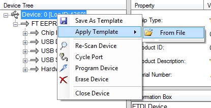
Execute MProg.exe from within the directory structure where you installed MPROG. You should see a screen like the one pictured below.
Select File- Open, and select the XDS100_wUART.ept file you extracted
Select Device- Scan to verify that it will talk to your XDS100
Select Device- Erase to erase the existing programming
Select Device- Program to program the correct settings
You should now be able to follow the directions Here to verify that it has been programmed correctly. If it has, you should now be able to use your XDS100 with CCS.
Q: Does the XDS100v2 latch data on the rising or falling edge.
Q: How do I tell what the CPLD version is on my XDS100v2.
A: Please contact your manufacturer. They may be able to tell from the manufacturing ID. There is no ID in the cpld code, so it cannot be determined by software.
Q: How can I update the CPLD on my XDS100v2.
A: If your manufacturer built the XDS100v2 according to the reference design, you will be able to upgrade the XDS100v2 CPLD via SW. If your manufacturer did not follow the XDS100v2 reference design, please contact your manufacturer directly.
As of 4/28/2010, an enhancment to improve reliability with devices which require Adaptive Clocking ex: ARM9 is included with the updated CPLD. The specific items implemented in this CPLD update are:
TCK loopback when a power loss is detected
Fixed definitions of certain signals from inout to output EMUs and TMS. T_SRST remains inout.
For XDS100v2 designs which have followed the TI reference design, the CPLD can be re-programmed through the USB by using the utility here. Usage instructions are included in the installation.
Blackhawk has placed XDS100v1/v2 updates here. This includes the CPLD update as well as instructions for updating a Blackhawk v1 USB100 device to v2.
Please note that this CPLD update is designed for use with CCS v4.1.1 and newer.
A: There is an issue in the FPGA VHDL released in the XDS100v3 Design Kit v1.0 on 1 June 2011 which inadvertently disables this feature. It will be corrected in the next XDS100v3 Design Kit update.
XDS100 v1.0 RTM SW: It is recommended that users upgrade to the latest versions of the XDS100 SW. Please check the Software section above. Do NOT install this if you are using CCS v3.3 SR12 or newer, a CCS which came with your C2000 Control Stick, or CCSv4.

TMS320-XDS100-V3 DSP and ARM emulator and adapter USER S MANUAL Revision F, March 2015 Designed by OLIMEX Ltd, 2013 All boards produced by Olimex LTD are.
The XDS200 family features a balance of low cost with good performance between the super low cost XDS100 and the high XDS200 USB Debug Probe: Serial Wire.
XDS100 v1 FTDI error in VM machine. invalid emulator serial number, also xds100 test reports all tests passed.
Choose the model of your device FTDI TI XDS100 Channel B - page 1 - FTDI TI XDS100 Channel B USB Universal Serial Bus USB/VID_0403 PID_a6d0 MI_01 and others.
XDS100 v1 and v2 DOWNLOADS Welcome to the Blackhawk XDS100 Support Area. This page This is a version 1 device and can also be identified by a serial number.
Can t install the TI XDS100 Channel A and Channel B drivers. The cause may be one or more of: invalid XDS100 serial number, blank XDS100 EEPROM.


